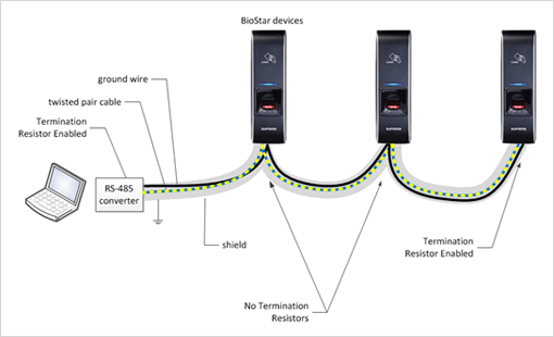
In an RS-485 daisy chain connection, it is crucial that the resistors are properly installed and the cable is an AWG 24 Twisted pair with Internal impedance of 120 Ohms :
RS-485
RS-485 signaling relies upon balanced and differential signaling schemes and has many advantages over unbalanced signaling, such as RS-232, such as strong noise immunity and multi-drop configuration capability. These are the most frequently asked questions on using RS-485 signaling systems, which are worth reading before designing an RS-485 BioStar network system.
Cable
The RS-485 transmission system requires twisted-pair cables for best results to maximize its noise rejection characteristics. The characteristic impedance of the cable is recommended to be 120 ohms.
Please DO NOT USE Ethernet cable but only below recommended cable.
| Cable | Size | Pairs | Impedance |
| Belden 9841 | 24 AWG Str (0.20 mm²) | 1 | 120 Ohms |
| Belden 9842 | 24 AWG Str (0.20 mm²) | 2 | 120 Ohms |
| Belden 82841 | 24 AWG Str (0.20 mm²) | 1 | 120 Ohms |
| Belden 82842 | 24 AWG Str (0.20 mm²) | 2 | 120 Ohms |
| Belden 89841 | 24 AWG Str (0.20 mm²) | 1 | 120 Ohms |
| Belden 89842 | 24 AWG Str (0.20 mm²) | 2 | 120 Ohms |
| Alpha Wire 6412 | 24 AWG Str (0.20 mm²) | 1 | 120 Ohms |
| Alpha Wire 6413 | 24 AWG Str (0.20 mm²) | 2 | 120 Ohms |
| General Cable C0841A | 24 AWG Str (0.20 mm²) | 1 | 120 Ohms |
| General Cable C0842A | 24 AWG Str (0.20 mm²) | 2 | 120 Ohms |
| Connect-Air W241P2050FRIB | 24 AWG Str (0.20 mm²) | 1 | 120 Ohms |
| CAE Groupe B9842NHT500 | 24 AWG Str (0.20 mm²) | 2 | 120 Ohms |
Termination
cable endsAs the cable gets longer, it acts as a transmission line, and the signals tend to reflect at the end of the line. To suppress this reflection, it is recommended to add termination resistors between signal pairs at both ends of the cable. The BioStar devices have onboard termination resistors that can be enabled through slide switches or software configuration, so you may enable them if a device is placed at one of the ends of the cable.
Use proper resistor for termination. The resistance should match the characteristic impedance of the cable. As the RS-485 system recommends 120-ohm cables, the BioStar devices have 120-ohm resistors on board.
Place at the right place. The resistors should be placed at both cable ends to suppress line reflection. DO NOT PLACE more than two termination resistors within a cable.
For BioStar 2 refer to the below article as well:
RS485 Mode (Master, Default, Slave)
Maximum Slave Devices
One master device can connect up to 31 slave devices, but up to 8 fingerprint devices can be connected through RS485.
We recommend a minimum number of RS-485 connected fingerprint devices, considering the number of users and connected devices.
This is because, depending on the device used as the master device, it can lead to a slow matching speed.
However, CS-40 has a different specification. It supports 5 RS-485 ports, up to 31 devices per port, and a maximum of 64 slave devices in total.
Sample CS-40 Configuration 1
Port 1: 31 slave devices
Port 2: 31 slave devices
Port 3: 2 slave devices
Sample CS-40 Configuration 1
Port 1: 10 slave devices
Port 2: 10 slave devices
Port 3: 10 slave devices
Port 4: 10 slave devices
Port 5: 24 slave devices
Daisy Chain

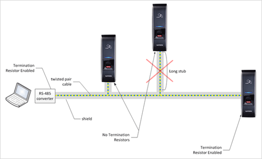
Avoid using long stubs for each node. Long stubs act as transmission lines and should be kept as short as possible if unavoidable.
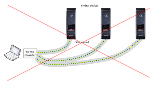
Do not use star-shaped wiring. This makes the transmission line system complicated and makes suppressing line reflections difficult, if not impossible.
CS-40 Sample Configuration:
- Install the termination resistor on each end of the daisy chain (red box)
- CS-40 has a internal termination resistor so turn the DIP switches on
[Device Manual]
Ground
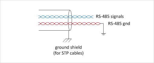
A common misunderstanding in an RS-485 network is that it only requires two-wire cables. This is wrong, and it requires a ground wire to equalize node voltage differences. Ground potential differences are harmful to signal quality and signal transceiver reliability, so they should be kept as low as possible within a network. A simple approach is to use ground wire at the cost of ground loop current.


